Creating a New Plugin
Plugins are an essential part of Rxn Rover, providing the ability to interface with, control, analyze, and communicate directly with connected devices. In this tutorial, we will walk through the process of creating a new plugin in RxnRover.
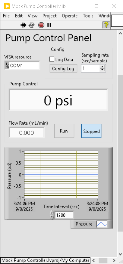
Mock Pump Controller Plugin main.vi showcasing the UI of a typical Rxn Rover plugin
Overview
Plugins in Rxn Rover typically interact with hardware devices; however, purely software-based plugins can exist too, like for reactor control algorithms, analytical tools, and simulation tools. Before you begin writing a plugin for a specific type of hardware, you’ll need to consider whether you require a custom device driver or if you can use an existing one. Some manufacturers might already provide a LabVIEW driver.
Note
All Rxn Rover plugins require the DynamicReentrant library to be installed. This library is provided by the Rxn Rover team to facilitate communication with Rxn Rover.
Creating a LabVIEW Device Driver
If the device does not already have a pre-existing driver, you’ll need to create one. Instrument drivers are responsible for handling the communication and control of the device with your computer.
For more detailed guidelines, refer to: Developing LabVIEW Plug and Play Instrument Drivers or see our tutorial on creating a driver
LabVIEW Driver Development Checklist:
Understand the communication protocol used by the device (e.g., USB, GPIB, Ethernet).
Test basic connectivity with the device.
Create functions for controlling and querying the device (e.g., setting parameters, reading data, etc.).
Handle errors and exceptions to ensure robust communication.
Creating a Plugin from the Template
Once you have your driver ready (or confirmed that one already exists), follow these steps to create the plugin:
Ensure you have correctly installed the DynamicReentrant library.
Download the Template
Download or clone the Generic Plugin Template from GitHub.
Extract the ZIP and rename the folder (recommended:
General Plugin Template).
Integrate into LabVIEW (optional but recommended)
Copy the extracted folder to:
<LabVIEW Data>/ProjectTemplates/Source/General Plugin TemplateMove the
general_plugin_template.xmlfile to:<LabVIEW Data>/ProjectTemplates/MetaData/
Create a New Plugin Instance
You can either:
Use the LabVIEW Project Creator to make a new project from the template.
Copy and rename the template folder.
Place your new plugin folder in:
<Documents>/RxnRover/CustomPluginsCustomize the Plugin
Rename
Generic Plugin Template.lvprojandRename to match project.lvlibto match your instrument.Edit
plugin.confto reflect your new plugin:Plugin name (We recommend naming it after your instrument; it can be anything non-blank)
Plugin type (Must be one of the Rxn Rover-supported and recognized plugin types)
Controller type (Must be one of the Rxn Rover-supported and recognized controller types)
Edit
Main.vi:Update the title and display units.
Follow the instructions on the front panel.
Adjust the numeric formatting of fields.
Set default values for all front panel controls.
Modifying the Plugin Template
Once you open Main.vi and navigate to the block diagram, you’ll see several parallel loops. Most modifications will be made in the following three loops:
Instrument Manager Loop (IML)
Acquisition Message Loop (AML)
Logging Message Loop (LML)
UI Manager Loop (UML) (only if you are changing the UI)
Note
If you are not changing the functionality of the plugin (write one setpoint, read one value, start, stop, etc.) you probably only need to change the Instrument Manager Loop (IML), Logging Message Loop (LML), and Acquisition Message Loop (AML).
IML Changes
In the Initialize case:
Modify the instrument state typedef according to the instructions in the code. This typedef represents the state of the instrument. For example, a heater plugin might include:
Temperature setpoint
Current temperature
Heating status
Error flags
For each state added, create a corresponding
Get Statemessage case in the IML. This allows the plugin to query the instrument for that information.Follow the instructions in the
--- Copy for Get State Messages ---case and refer to the example cases listed below it in the case structure.Modify the following cases to integrate with your specific instrument:
Start InstrumentStop InstrumentChange Setpoint
In the
Set VISA Resourcecase, update theInit.vi -> Connectingcase to correctly verify and initialize the instrument connection.
AML Changes
In the Initialize case of the AML:
Modify, add, or remove items in the Acquisition Messages array. Each item should trigger a corresponding message case in the IML.
Ensure all messages exactly match the IML case names.
Make sure that the
Reportmessage is the last item in the array.
LML Changes
In the Initialize case of the LML:
Update the
Channelsarray to correspond to the instrument states listed in the AML’s Acquisition Messages array.This ensures the correct data is logged to the CSV file.
UML Changes (only if you are changing the UI)
The UI Manager Loop (UML) along with the Data Display Loop (DDL) handles the showing of data updates / user interaction (Ex. button presses) on the front panel of Main.vi.
In the Initialize case of the UML:
Ensure that all front planel control/indicators are properly linked to the
UI Data.ctltypedef.Ensure that all front panel controls/indicators are properly reference via
VI Server References
Inside of the Event Handling Loop (EHL):
Add event cases for any new front panel controls you add to
Main.vi
In the Data Display Loop (DDL):
Ensure that the variables inside Instrument State cluster you want to display are properly linked to the controls / indicators on the front panel of
Main.vi
Note
If any part of this tutorial is unclear, please feel free to look at other Plugin examples in our Public GitHub Repositories or reach out to us by making a discussion on Rxn Rover’s GitHub Discussion Board
Follow the tutorial on creating a VIPM package to package your plugin for automated installation and distribution. After creating your plugin consider making a submission to the Rxn Rover Plugin Catalog